Dc Motor Wiring Diagram 2 Wire
4 wire reversible psc motor with a triple pole double throw switch. Injunction of two wires is usually indicated by black dot at the junction of two lines.
DC Motor Reversing Circuit Timer or Remote Control Quasar Electronics

1 trick that we 2 to printing a similar wiring plan off twice.
Dc motor wiring diagram 2 wire. Preferably one with a center off position, so you can control the motor like this: Pwm offers precise control over the motor’s speed and torque. Now the capacitor is permanently wired into the winding.
If not, the arrangement will not work as it should be. Refer to the motor manufacturer’s data on the motor for wiring diagrams on standard frame ex e, ex d etc. 1 trick that we 2 to printing a similar wiring plan off twice.
Wire connection of brushless dc motor. Use figure 2 if your motor has a dual voltage shunt field. Since the wiring diagram does not specify ac line lead polarities, the connection may be made to either side of the ac line (i.e.
On somfy motor wiring diagram. Each component ought to be set and connected with other parts in specific way. Next, an explanation of the coil connection method used in brushless dc motors.
When we flip the switch to the left terminal 1 the dc fan runs while the dc motor does not. The sonesse 40 wt is an ac motor and requires a vac supply feed across the neutral and one. Overload relays ac motors dc motors wiring capacitors.
Washing machine universal motor wiring. One method is to connect the coils in a loop as we compared it with the rotor winding of dc motors in fig. Inst maint & wiring_5.qxd 20/11/2015 11:37 am page 6
As illustrated, the relays have to be dc, same coil voltage as the motor, but the bottom can be separated and fed from a different voltage. The wiring diagram above is similar to the ones shown earlier. Relay switch 6 terminal atv winch motor smittybilt solenoid wiring diagram 12 volt dc 100 amp reversing polarity 12vdc post albright 33 ramsey 2 usvi dc66 11p 12v valve with 3 wire maxwell dual.
They are usually clearly marked with a and f so there's no confusion. The interlocks are specially important, because if both relays are on, it would be a short circuit. This will cause the motors to malfunction.
Two additional switches have been inserted. When you make use of your finger or perhaps the actual circuit with your eyes, it is easy to mistrace the circuit. Electrical wiring diagrams for air.
2 — installation & wiring: A power supply that suits the specs of the motor (has the voltage and amperage as the manufacturer of the motor recommends). 2 speed, 2 winding, single voltage, wye connected, with current transformers, lightning arrestors & surge capacitors;
Various types of throttles can be used; These diagrams are current at the time of publication, check the wiring diagram supplied with the motor. This is important because a.
If you have a dc drive, the manual that comes with it should give you a diagram showing you how to connect the motor to the drive. Ac80, ac90, ac100 single phase motors. Motor connections your motor will be internally connected according to one of the diagrams shown below.
Use figure 1 if your motor has a single voltage shunt field. Wiring a 3 wire solenoid valve to the w100 controller. Coil suppression diodes should be used on the main and forward/reverse contactors, as shown.
Connect the other side of the capacitor to the black lead from the motor/gearmotor, and one of the hot leads from the ac motor cord (see wiring diagram). The circuit uses 2 relays, 2 limit switches, and a dc motor. When you make use of your finger or perhaps the actual circuit with your eyes, it is easy to mistrace the circuit.
Wiring diagram book a1 15 b1 b2 16 18 b3 a2 b1 b3 15 supply voltage 16 18 l m h 2 levels b2 l1 f u 1 460 v f u 2 l2 l3 gnd h1 h3 h2 h4 f u 3 x1a f u 4 f u 5 x2a r power on optional x1 x2115 v 230 v h1 h3 h2 h4 optional connection electrostatically. Also 2 one way switches in which one is used to turn motor rotation. Dc motor wiring diagram from www.electricaltechnology.org print the wiring diagram off plus use highlighters to trace the signal.
In my case it was 2 aa batteries. 3 pin toggle switch wiring extended wiring diagram. Unipolar motors use coils that are.
To make it move, you have to drive it with a stepper motor controller. This method is called a δ (delta) connection. Two connection methods are used for brushless dc motors.
Wye start delta run or pws connection, 12 lead, dual voltage: Do not wire two or more lt operators to one single pole switch.
Two Wire & Three Wire Motor Control Circuit Motor Control Circuit Diagram Electrical A2Z
switches Circuit for a DC motor with 2 microswitches reversing direction Electrical

12V 24V PWM DC Motor Stepless Variable Speed Controller Switch with Metal Shell eBay

Two Speed Motor Wiring

theLEDwheel How to wiring dual motors on your Crawler

Fig.6 Split Phase Motor Wiring Diagram Electrical A2Z
3 Phase Two Speed Motor Wiring Diagram

Century 2 Speed Motor Wiring Diagram Free Wiring Diagram

How to Wire Hydraulic Power Pack,Power Unit Diagram Design

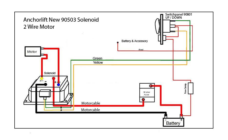
12v Reverse Solenoid for Windlass Motors with 2 Posts AnchorLift Direct
Century 2 Speed Motor Wiring Diagram Sample Wiring Collection

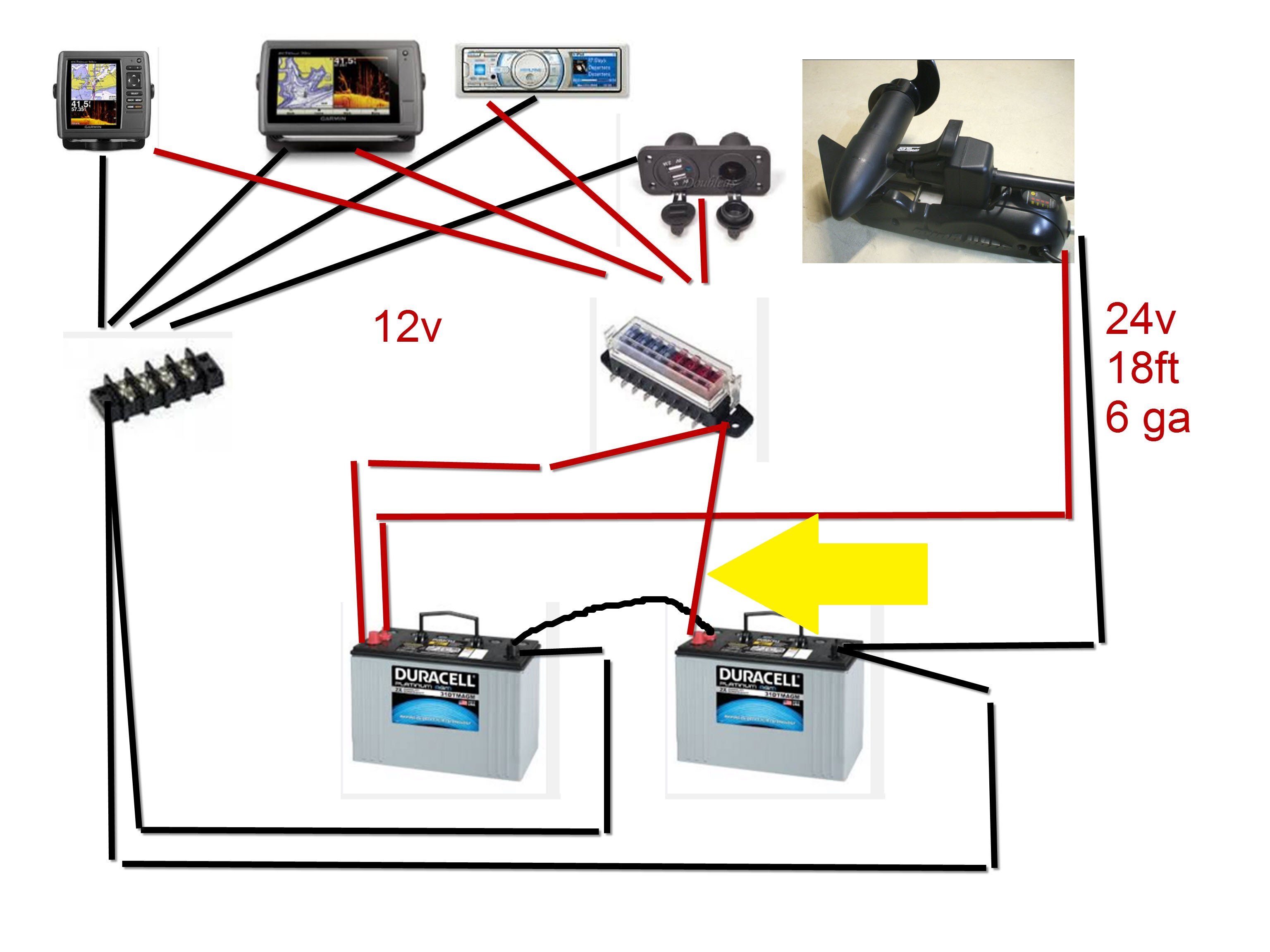
Your thoughts on this trolling motor accessories wiring? General Discussion Forum InDepth
transformer Old variable speed AC motor wiring Electrical Engineering Stack Exchange

50 Awesome 2 Speed Fan Wiring Diagram
2 Speed Motor Wiring Diagram

current in order to understand bldc motors and their working principle, I read a lot on the

18+ Ge 1 2 Hp Electric Motor Wiring Diagram Wiring Diagram Electric motor

Pin on DIY ALARM VIDEO TECH

3/4 HP 1 Speed Motor Triangle Engineering, Inc.
